000
23.03.2008, 22:45 Uhr
Guido
Default Group and Edit

|
Hallo,
nachdem ich seit Tagen flach liege (irgendein Virus) ging es heute endlich mal wieder aufwärts. Beim Blick auf den Kalender fällt mir dann auf, dass das Klubtreffen bald ran ist. Im letzten Jahr hatte ich mir vorgenommen ein lange brach liegendes Projekt endlich anzugehen. Naja das Jahr war schnell vorbei....
So, genug geseiert....
Was habe ich hier?

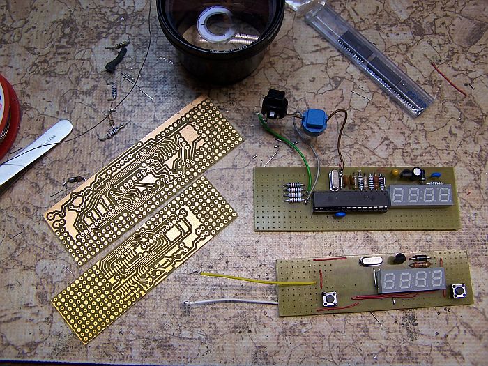
Richtig! Einiges Geraffel, zwei schöne Platinen und die beherbegen meinen "MultiTool2"

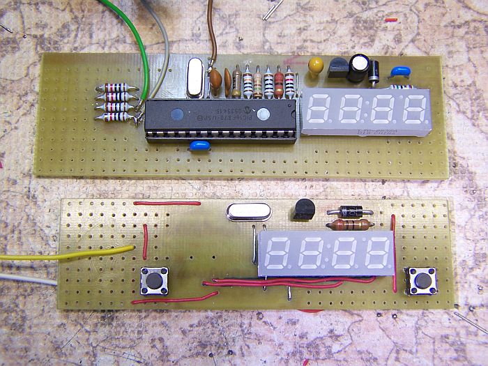
Hier nochmal in einer Nahaufnahme. Oben in konventioneller Bauweise, unten soweit es geht als SMD.
Was kann das Teil nun? Seht selbst: (Übersetzung kommt später)
--------------------------------------------------------
Here are how each of the modes work at present....
Prob - Logic Probe
The logic probe shows 'H' for high (over 3.7 volts), 'L' for low (below 0.8 volts) and '-' for floating in the first display location. If a pulse is detected (0.5 usec minimum), the second location flashes a 'P'.
PULS - logic pulser
The logic pulser shows the pulse rate (5, 50, 500, 5.0) in the last 3 locations. The first location shows the sensed logic level as a dash in the bottom or top of the digit. When button #1 is held down, a series of 0.5 microsecond pulses are generated in the opposite direction and the center segment is lit. Pushing button #2 cycles thru the 4 pulse rates. The selected pulse rate is saved on power down.
FrEq - Frequency Counter
In the frequency counter mode, hitting button #1 switches the display to the next 4 digits of the count. For instance, the display shows '12.57' for a frequency of 12,576 hz. Holding down button #1 shows '2576' - the lowest 4 digits. If a decimal point shows, the value is in Khz, if the decimal is flashing, the value is in Mhz. Hence, a frequency of 42,345,678 hz is displayed as 42.34 with a flashing decimal. Holding down button #1 in this case will display 5678.
Cnt - Event Counter
In the event count mode, the display shows the lowest 4 digits. Button #1 switches to the next higher 4 digits while held down. Button #2 resets the count.
VoLt - Voltmeter
The voltmeter uses the power going into the probe as a voltage reference. The current implementation shows only an approximate voltage - about 2% high. This can still be very usefull for most measurements. Do not connect the probe to voltages that exceed 5 volts under any conditions.
diod - Diode Junction Voltage
This is just the voltmeter function with 10k resitor feeding current to the probe tip. When a diode or transistor junction is connected from the tip to the ground lead, the drop voltage is displayed.
Cap - Capacitance Measurement
When a capacitor is connected from the tip to the ground lead, and button #1 is pushed, its value is displayed. Values from .001 uf to about 500 uf are displayed. The larger the capacitor, the longer it takes to measure. A value of 100uf takes a couple of seconds.
SIG - Signal Generator
This mode generates a 500hz squarewave at about 0.5 volts. The signal is only generated while button #1 is held down.
ntSC - Video Patern
Generates an NTSC video frame with a white dot pattern when button #1 is held down.
9600 - Serial Ascii
Each time button 1 is pushed, the letters A-Z followed by cr/lf is generated. Auto polarity sensing. If the signal injection point is orignally high, then normal (zero start bit) ascii is generated. Otherwise, the other polarity is done. New feature: Button #2 cycles thru 1200, 2400, 4800, 9600 baud.
Midi - Midi Note
Sends note number 60 (middle C) on any of the 16 midi channels. Holding button 1 sends 'note on'. Release of button 1 sends 'note off'. Buttton 2 cycles thru the 16 channels. The midi channel number is stored.
R/C Servo
Generates 1ms to 2ms pulse for r/c servos. Button 1 increases pulse, Button 2 decreases pulse. Defaults to 1.5 ms each time mode is entered.
[ ] Sqaure Wave
Generates 1 - 9999 hz squarewave. Button 1 decreases frequency, Button 2 increases frequency.
Prn - Pseudo Random Number
Generates 10khz digital PRN series.
ir38
Generates 1 millisecond on and 2.5 millisecond off of 38khz square wave. When connected to IR LED, used for testing IR reciever modules.
PWM
Generates variable pulse width 3-97 percent of a 6khz (approx) digital signal. Button 1 decreases pulse width, Button 2 increases pulse width.
In any mode, holding down both buttons exits to the menu. Once there, releasing and pressing button #1 cycles thru its modes forward. New Feature: Button #2 cycles thru modes backwards.
The mode is saved on power down. Since this device takes its power from the circuit being tested, powering down and back up will restore the same operating mode.
-------------------------------------------
Bisher habe ich folgendes getestet
Voltmeter (bis max. 5V ca. 1%) zur überprüfung der TTL-Spannung völlig ausreichend
Frequenzzähler
habe von 10Hz bis 45MHz (TTL-Pegel) angelegt, 1A!
Logikprüfer
Geht wir versprochen
Diodenprüfer
Zeit die Flussspannung recht genau an, Si-, Germanium-, Shottky-Dioden lassen sich prima auseinanderhalten (grade bei den kleinen Glasmörkeln wichtig) LEDs lassen sich auch testen und da mit 5V getestet wird, sogar noch blaue und weisse.
Kondensatortester
Zeigt bei offener Prüfspitze 100p an, ab ca. 1nF bis zu 470µF geht sehr genau, ab ca. 100µF dauerts aber etwas...
R/C-Servotester
Gibt sehr genaue Impulslänge von 0,77nS bis 2,3nS aus.
Die anderen Funktionen habe ich mal kurz angetestet, wobei das ntSC-Geraffel hier in "PAL-Land" daneben ist.
Morgen (so mein Kadaver mitspielt) bastel ich das Gehäuse für die SMD-Version.
Und wenn Interesse besteht: Ein paar Platinen habe ich noch, einige programmierte Chips auch 
Guido
--
Der Mensch hat drei Wege, klug zu handeln.
Erstens durch Nachdenken: Das ist der edelste.
Zweitens durch Nachahmen: Das ist der leichteste.
Drittens durch Erfahrung: Das ist der bitterste.
Konfuzius
Wer immun gegen ein Minimum an Aluminium ist, der hat eine Aluminiumminimumimmunitität.
Dieser Beitrag wurde am 23.03.2008 um 23:24 Uhr von Guido editiert. |
